
Are you looking for a way to understand and maintain your vehicle’s health without relying solely on expensive mechanics? In today’s automotive world, vehicles are more complex than ever, incorporating sophisticated electronic systems that control everything from engine performance to safety features. Understanding these systems requires the right tools, and that’s where the Multi Standard Car Scan Tool comes into play.
This guide will delve into the world of multi standard car scan tools, explaining how they go beyond basic diagnostics to offer a comprehensive solution for modern vehicle maintenance. We’ll explore the foundation of these tools – the OBD2 protocol – and how multi standard capabilities are essential for addressing the evolving landscape of automotive technology.
Understanding OBD2: The Diagnostic Foundation
OBD2, or On-Board Diagnostics version 2, is essentially your car’s built-in self-diagnostic system. It’s a standardized protocol that allows you to access vital information about your vehicle’s performance and health through a universal OBD2 connector.
You’ve likely encountered OBD2 indicators without even realizing it. That “check engine light” illuminating on your dashboard? That’s your car signaling an issue detected by the OBD2 system. When you take your car to a repair shop, the mechanic’s first step often involves using an OBD2 scanner to pinpoint the problem.
This process is straightforward: the mechanic connects the OBD2 reader to the 16-pin OBD2 connector, usually located near the steering wheel. The scan tool then sends “OBD2 requests” to the car’s computer, and the car responds with “OBD2 responses.” These responses can contain a wealth of data, including speed, fuel level, and crucially, Diagnostic Trouble Codes (DTCs). DTCs are like error messages that help mechanics quickly diagnose and address vehicle issues.
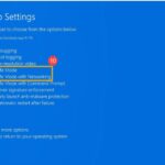
Understanding OBD2: The malfunction indicator light (MIL), often called the “check engine light,” is a key indicator of issues detectable by a multi standard car scan tool.
Does Your Car Use OBD2? Likely, Yes.
The good news is that OBD2 is widely adopted. Almost all non-electric cars manufactured in recent decades support OBD2, and many utilize the CAN bus communication system as their foundation. However, it’s worth noting that older vehicles, even those with a 16-pin connector that resembles an OBD2 port, might not actually be fully OBD2 compliant.
To determine if your car is OBD2 compliant, consider its origin and year of manufacture:
OBD2 Compliance Guide: This chart helps determine OBD2 compliance based on vehicle origin and manufacturing dates, relevant when choosing a multi standard car scan tool.
A Brief History of OBD2: From Emissions to Essential Diagnostics
The story of OBD2 begins in California. Driven by the California Air Resources Board (CARB), OBD systems were mandated in all new cars sold in California from 1991 onwards, primarily for emission control.
The Society of Automotive Engineers (SAE) played a crucial role in standardizing the protocol, leading to the OBD2 standard. This standardization included Diagnostic Trouble Codes (DTCs) and the universal OBD connector, ensuring compatibility across different vehicle manufacturers (SAE J1962).
The OBD2 standard was then progressively implemented globally:
- 1996: OBD2 became mandatory in the USA for cars and light trucks.
- 2001: The European Union (EU) mandated OBD2 for gasoline cars (EOBD).
- 2003: EOBD was extended to diesel cars in the EU.
- 2005: OBD2 became required in the US for medium-duty vehicles.
- 2008: US vehicles were required to use ISO 15765-4 (CAN) as the underlying protocol for OBD2 communication.
- 2010: OBD2 mandates were extended to heavy-duty vehicles in the US.
OBD2 History and Evolution: Tracing the development of OBD2 from emission control origins to its current diagnostic capabilities, highlighting the need for versatile tools.
OBD2 Timeline: A visual representation of key milestones in OBD2 history, demonstrating its increasing importance in vehicle diagnostics and repair.
The Future of OBD: OBD3 and remote diagnostics are anticipated advancements, showcasing the ongoing evolution of vehicle diagnostic technologies.
The Future of OBD: Adapting to Modern Vehicles and Data Needs
While OBD2 remains a cornerstone of vehicle diagnostics, the automotive landscape is shifting. Let’s look at some key trends shaping the future of OBD and the role of multi standard car scan tools:
Initially designed for emissions testing, legislated OBD2 has a notable exception: electric vehicles (EVs). Interestingly, most modern EVs are not required to, and often do not, support standard OBD2 requests. Instead, they frequently utilize OEM-specific UDS (Unified Diagnostic Services) communication protocols. This makes accessing data from EVs challenging unless the proprietary protocols are reverse-engineered. However, advancements are being made in reverse engineering, as seen in case studies for brands like Tesla, Hyundai/Kia, Nissan, and VW/Skoda EVs.
OBD2’s limitations in data richness and reliance on older communication protocols have spurred the development of enhanced alternatives. WWH-OBD (World Wide Harmonized OBD) and OBDonUDS (OBD on UDS) are emerging protocols designed to improve OBD communication by building upon the more advanced UDS protocol. These advancements emphasize the growing need for multi standard car scan tools capable of handling these newer protocols alongside traditional OBD2.
In our increasingly connected world, traditional OBD2 testing methods can seem outdated. Manual emission checks are time-consuming and costly. The proposed solution? OBD3 – integrating telematics into vehicles.
OBD3 envisions adding a small radio transponder to vehicles, similar to those used for bridge tolls. This technology would allow for the wireless transmission of the vehicle identification number (VIN) and DTCs to a central server for automated checks. While devices like the CANedge2 WiFi CAN logger and CANedge3 3G/4G CAN logger already facilitate data transfer via WiFi/cellular, the widespread adoption of OBD3 raises political and privacy concerns related to surveillance.
The original purpose of OBD2 was for stationary emission controls in repair shops. However, its use has expanded significantly, with third parties utilizing OBD2 for real-time data generation through OBD2 dongles, CAN loggers, and other devices. Interestingly, the German car industry has expressed intentions to limit third-party access to OBD2 data, arguing that it was not designed to enable a data-driven economy outside of manufacturer control. This perspective suggests a potential future where manufacturers may seek to control vehicle data access more tightly, possibly by “turning off” OBD2 functionality during driving and centralizing data collection. Such a move could reshape the market for third-party OBD2 services.
EV Diagnostics and OBD2: Electric vehicles often deviate from traditional OBD2, highlighting the need for multi standard car scan tools to address diverse vehicle communication protocols.
Become a Diagnostics Expert: The Ultimate CAN Guide
Want to deepen your understanding of vehicle communication networks?
Our comprehensive ‘Ultimate CAN Guide’ provides 12 detailed introductions in a 160+ page PDF resource.
Download now
The Ultimate CAN Bus Guide: A valuable resource for expanding your knowledge of Controller Area Network (CAN) bus systems, essential for advanced vehicle diagnostics.
OBD2 Standards: Defining the Communication Framework
Think of OBD2 as a high-level language for vehicle diagnostics, while CAN (Controller Area Network) bus is the communication method, like a phone line. OBD2 operates similarly to other CAN-based higher-layer protocols such as J1939, CANopen, and NMEA 2000.
OBD2 standards comprehensively specify various aspects of vehicle diagnostics, including the OBD2 connector itself, the underlying communication protocols, OBD2 Parameter IDs (PIDs), and more.
These standards can be visualized within a 7-layer OSI model framework. Notably, both SAE (primarily US standards) and ISO (international standards) cover multiple layers, often with technically equivalent standards like SAE J1979 vs. ISO 15031-5 and SAE J1962 vs. ISO 15031-3.
OBD2 and CAN Bus in the OSI Model: Illustrating how OBD2 and CAN bus protocols fit within the 7-layer OSI model, providing context for understanding vehicle communication standards.
OBD2 Connector Pinout: Diagram of a Type A OBD2 connector, highlighting pin assignments and their role in vehicle diagnostics, crucial for understanding scan tool connections.
The OBD2 Connector: Your Access Point [SAE J1962]
The 16-pin OBD2 connector is your physical interface for accessing vehicle data. Standardized under SAE J1962 / ISO 15031-3, it provides a consistent connection point across vehicles. The illustration above depicts a typical Type A OBD2 pin connector, also known as a Data Link Connector (DLC).
Key features of the OBD2 connector:
- Location: Usually near the steering wheel, but sometimes hidden behind panels.
- Pin 16: Provides battery power, often active even when the ignition is off.
- Pinout: Varies depending on the communication protocol used by the vehicle.
- CAN bus: In CAN bus systems, pins 6 (CAN-H) and 14 (CAN-L) are the communication lines.
OBD2 Connector Types: A vs. B
You might encounter Type A and Type B OBD2 connectors. Type A is standard in cars, while Type B is more common in medium and heavy-duty vehicles.
While both types share similar pinouts, they differ in power supply (12V for Type A, 24V for Type B) and often in baud rate (cars typically use 500K, heavy-duty vehicles often 250K, sometimes 500K).
Type B connectors have a distinguishing interrupted groove in the middle. A Type B OBD2 adapter cable will be compatible with both Type A and Type B sockets, but a Type A adapter will not fit into a Type B socket.
OBD2 Connector Types A and B: Illustrating the differences between Type A and Type B OBD2 connectors, including voltage and physical characteristics, important for tool compatibility.
OBD2 and CAN Bus Relationship: Visual representation of the relationship between OBD2 as a diagnostic protocol and CAN bus as the communication network, essential for understanding multi standard car scan tool functionality.
OBD2 and CAN Bus: The Communication Backbone [ISO 15765-4]
Since 2008, CAN bus has been the mandatory lower-layer protocol for OBD2 in all US-sold vehicles, as defined by ISO 15765.
ISO 15765-4, also known as Diagnostics over CAN (DoCAN), specifies how OBD2 communication is implemented on a CAN bus network (ISO 11898). It standardizes the CAN interface for diagnostic equipment, focusing on the physical, data link, and network layers:
- CAN bus bit rate: Must be 250K or 500K.
- CAN IDs: Can be 11-bit or 29-bit.
- Specific CAN IDs: Reserved for OBD requests and responses.
- Diagnostic CAN frame data length: 8 bytes.
- OBD2 adapter cable: Maximum length of 5 meters.
OBD2 CAN Identifiers: 11-bit and 29-bit
OBD2 communication relies on request and response message exchanges.
In most cars, 11-bit CAN IDs are used for OBD2. The ‘Functional Addressing’ ID 0x7DF is used to query all OBD2-compatible ECUs (Electronic Control Units) for data related to a requested parameter (ISO 15765-4). ‘Physical Addressing’ requests to specific ECUs can be made using CAN IDs 0x7E0-0x7E7, though this is less common.
ECUs respond using 11-bit IDs in the range 0x7E8-0x7EF. The most frequent response ID is 0x7E8 (from the ECM, Engine Control Module), followed by 0x7E9 (from the TCM, Transmission Control Module).
Some vehicles, particularly vans and medium/heavy-duty vehicles, may utilize extended 29-bit CAN identifiers for OBD2 communication instead of 11-bit IDs. In these cases, the ‘Functional Addressing’ CAN ID is 0x18DB33F1. Responses are typically seen with CAN IDs ranging from 0x18DAF100 to 0x18DAF1FF (often 18DAF110 and 18DAF11E). The response ID can also be represented in the ‘J1939 PGN’ format, specifically PGN 0xDA00 (55808), which is designated as ‘Reserved for ISO 15765-2’ in the J1939-71 standard.
OBD2 Request and Response Frames: Illustrating the structure of OBD2 communication frames, including request and response messages, essential for understanding data exchange with a multi standard car scan tool.
OBD2 CAN Bus Identifiers: Table outlining common CAN identifiers used in OBD2 communication, including functional and physical addressing IDs, crucial for configuring advanced scan tools.
OBD2 vs. Proprietary CAN Bus Data: Comparing standardized OBD2 data with OEM-specific CAN bus data, highlighting the expanded diagnostic capabilities of multi standard car scan tools.
OBD2 vs. Proprietary CAN Protocols: Expanding Diagnostic Horizons
It’s crucial to understand that a vehicle’s ECUs operate using OEM-specific proprietary CAN protocols, independently of OBD2. These protocols are unique to each vehicle manufacturer, model, and year. Typically, this OEM-specific CAN data is inaccessible to those outside the manufacturer’s network unless it is reverse-engineered.
When you connect a CAN bus data logger to your car’s OBD2 connector, you might observe OEM-specific CAN data being broadcast, often at high rates (1000-2000 frames/second). However, many newer vehicles incorporate a ‘gateway’ that restricts access to this proprietary CAN data through the OBD2 port, allowing only standardized OBD2 communication.
Therefore, think of OBD2 as a supplementary, standardized higher-layer protocol that runs parallel to the vehicle’s core OEM-specific communication network. A multi standard car scan tool bridges this gap by offering capabilities beyond basic OBD2, potentially accessing and interpreting OEM-specific data for more in-depth diagnostics.
Bit-rate and ID Validation: Ensuring Communication Compatibility
As discussed, OBD2 can utilize two bit rates (250K, 500K) and two CAN ID lengths (11-bit, 29-bit), resulting in four possible combinations. Modern cars commonly use 500K and 11-bit IDs. A robust multi standard car scan tool should systematically verify these parameters to ensure proper communication.
ISO 15765-4 outlines a recommended initialization sequence to determine the correct combination. This process leverages the mandatory support for a specific OBD2 request (mode 0x01 PID 0x00) in OBD2-compliant vehicles and the fact that incorrect bit rate transmission will generate CAN error frames.
Newer versions of ISO 15765-4 account for vehicles supporting OBD communication via OBDonUDS instead of OBDonEDS. While this article primarily focuses on OBD2/OBDonEDS (OBD on Emission Diagnostic Service as per ISO 15031-5/SAE J1979), WWH-OBD/OBDonUDS (OBD on Unified Diagnostic Service as per ISO 14229, ISO 27145-3/SAE J1979-2) is increasingly relevant, especially in EU trucks and buses.
To test for OBDonEDS vs. OBDonUDS, advanced scan tools may send UDS requests with 11-bit/29-bit functional address IDs for service 0x22 and data identifier (DID) 0xF810 (protocol identification). Vehicles supporting OBDonUDS should have ECUs that respond to this DID.
Currently, OBDonEDS (OBD2, SAE OBD, EOBD, ISO OBD) is prevalent in most non-EV cars, while WWH-OBD is primarily used in EU commercial vehicles. A truly multi standard car scan tool should be able to handle both.
OBD2 Bit-Rate and CAN ID Validation Flowchart: Illustrating the process for validating bit-rate and CAN ID configurations, ensuring compatibility for effective diagnostics with a multi standard car scan tool.
OBD2 Lower-Layer Protocols: Overview of the five lower-layer protocols used in OBD2 communication, highlighting CAN (ISO 15765) and older protocols, relevant for compatibility considerations in scan tools.
Five Lower-Layer OBD2 Protocols: A Legacy of Communication Methods
While CAN bus dominates modern OBD2 systems (ISO 15765), older vehicles (pre-2008) may utilize one of four other lower-layer protocols. Understanding these protocols is helpful when working with older cars and can be indicated by the OBD2 connector pinout.
- ISO 15765 (CAN bus): Mandatory in US cars since 2008 and now the most common globally.
- ISO14230-4 (KWP2000): Keyword Protocol 2000, common in 2003+ Asian vehicles.
- ISO 9141-2: Used in EU, Chrysler, and Asian cars (2000-2004).
- SAE J1850 (VPW): Variable Pulse Width, primarily in older GM cars.
- SAE J1850 (PWM): Pulse Width Modulation, primarily in older Ford cars.
ISO-TP: Transporting OBD2 Messages Beyond 8 Bytes [ISO 15765-2]
OBD2 communication on CAN bus utilizes ISO-TP (ISO 15765-2), a transport protocol, to handle messages larger than the 8-byte CAN frame limit. This is essential for transmitting data like Vehicle Identification Numbers (VINs) and Diagnostic Trouble Codes (DTCs). ISO-TP provides segmentation, flow control, and reassembly mechanisms for these larger payloads. For a deeper understanding, refer to our introduction to UDS.
In many cases, OBD2 data fits within a single CAN frame. ISO 15765-2 defines ‘Single Frame’ (SF) usage, where the first data byte (PCI field) indicates the payload length (excluding padding), leaving 7 bytes for OBD2-related data.
ISO-TP Frame Types for OBD2: Diagram illustrating different ISO-TP frame types used in OBD2 communication, including Single Frame, First Frame, Consecutive Frame, and Flow Control Frame, essential for handling multi-frame diagnostic messages.
Decoding the OBD2 Diagnostic Message [SAE J1979, ISO 15031-5]
To understand OBD2 communication on CAN at a deeper level, let’s examine a raw ‘Single Frame’ OBD2 CAN message. In simplified terms, an OBD2 message consists of a CAN identifier, a data length indicator (PCI field), and the data payload. The payload is further structured into Mode, Parameter ID (PID), and data bytes.
OBD2 Message Structure Breakdown: Detailed breakdown of the OBD2 message structure, showing the position of Mode, PID, and data bytes within a CAN frame, crucial for interpreting raw diagnostic data.
Example: OBD2 Request and Response in Action
Consider this example of requesting and receiving vehicle speed data:
A scan tool sends a request message with CAN ID 0x7DF and a 2-byte payload: Mode 0x01 and PID 0x0D (for Vehicle Speed). The car responds with CAN ID 0x7E8 and a 3-byte payload, including the speed value in the 4th byte (0x32, which is 50 in decimal).
By consulting the OBD2 PID specifications for PID 0x0D, we can determine that the value 50 corresponds to a physical speed of 50 km/h. Understanding this request-response mechanism is fundamental to using a multi standard car scan tool effectively.
OBD2 Request and Response Example (Vehicle Speed): Illustrating a request for vehicle speed (PID 0x0D) and the corresponding response, showing the CAN IDs and data payload structure in a practical scenario.
OBD2 PID Example – Vehicle Speed (0D): Detailed explanation of PID 0x0D (Vehicle Speed), showing the request and response data bytes and how to interpret the speed value.
OBD2 Services (Modes): Overview of the 10 standardized OBD2 service modes, including their functions for accessing current data, freeze frame information, and diagnostic trouble codes.
The 10 OBD2 Services (Modes): Accessing Diagnostic Functions
OBD2 defines 10 diagnostic services, also referred to as modes. Mode 0x01 is used to access real-time data, while other modes are used for retrieving and clearing Diagnostic Trouble Codes (DTCs), accessing freeze frame data, and more.
It’s important to note that vehicles are not required to support all 10 OBD2 modes. They may also implement OEM-specific modes beyond the standard set.
In OBD2 messages, the mode is specified in the second byte of the payload. In a request message, the mode is included directly (e.g., 0x01). In a response, 0x40 is added to the requested mode value (e.g., a response to mode 0x01 will start with 0x41). A multi standard car scan tool typically provides easy access to these modes through its user interface.
OBD2 Parameter IDs (PIDs): Requesting Specific Data
Within each OBD2 mode, Parameter IDs (PIDs) are used to request specific data points.
For example, mode 0x01 contains approximately 200 standardized PIDs that provide real-time data on parameters like speed, RPM, and fuel level. However, individual vehicles may only support a subset of the PIDs within a given mode.
One PID holds special significance: PID 0x00 in mode 0x01. If an emissions-related ECU supports any OBD2 services, it must support mode 0x01 PID 0x00. Responding to this PID, the ECU indicates which PIDs in the range 0x01-0x20 it supports. PID 0x00 serves as a fundamental ‘OBD2 compatibility test’. Similarly, PIDs 0x20, 0x40, …, 0xC0 can be used to determine support for subsequent ranges of mode 0x01 PIDs. A multi standard car scan tool often uses PID 0x00 to automatically detect supported PIDs.
OBD2 Request and Response Frames (PID Focus): Re-emphasizing the role of PIDs in OBD2 communication, highlighting how PIDs specify the data parameters being requested and returned by the vehicle.
OBD2 PID Overview Tool: Screenshot of an OBD2 PID overview tool, illustrating how these tools aid in understanding and utilizing OBD2 PIDs for effective vehicle diagnostics.
Tip: Utilizing an OBD2 PID Overview Tool
SAE J1979 and ISO 15031-5 appendices provide scaling information for standard OBD2 PIDs, allowing you to convert raw data into physical values. Our OBD2 PID overview tool simplifies this process, helping you construct OBD2 request frames and dynamically decode responses.
OBD2 PID overview tool
Practical OBD2 Data Logging and Decoding
Let’s illustrate how to log OBD2 data using a CANedge CAN bus data logger as a practical example. The CANedge allows custom CAN frame transmission, making it suitable for OBD2 logging. Connecting it to your vehicle is easy with an OBD2-DB9 adapter cable. Similar principles apply when using a multi standard car scan tool with data logging capabilities.
OBD2 Data Logger Setup: Diagram showing the setup for logging OBD2 data, including the connection of a data logger to the OBD2 port and the flow of request and response messages.
Supported PIDs Validation: Example of reviewing responses to ‘Supported PIDs’ requests in asammdf software, identifying the PIDs supported by a vehicle.
Step 1: Bit-rate, ID, and Supported PID Validation
As per ISO 15765-4, determine the vehicle’s bit rate and CAN IDs. The CANedge, like many multi standard car scan tools, allows you to perform these validation steps:
- Test 500K bit rate: Send a CAN frame at 500K and check for successful transmission. If unsuccessful, try 250K.
- Use identified bit rate for subsequent communication.
- Send multiple ‘Supported PIDs’ requests and analyze responses.
- Determine 11-bit vs. 29-bit IDs based on response IDs.
- Identify supported PIDs based on response data.
Plug-and-play configurations are often available to streamline these tests. Most post-2008 non-EV cars support 40-80 PIDs using 500K bit rate, 11-bit CAN IDs, and the OBD2/OBDonEDS protocol.
The asammdf GUI screenshot illustrates multiple responses to a single OBD request (using ID 0x7DF), as it polls all ECUs. Since all OBD2/OBDonEDS-compliant ECUs must support service 0x01 PID 0x00, numerous responses are common for this PID. Subsequent ‘Supported PIDs’ requests typically elicit fewer responses. The ECM ECU (0x7E8) often supports all PIDs supported by other ECUs in the example, suggesting that bus load can be reduced by directing requests specifically to the ECM (using ‘Physical Addressing’ CAN ID 0x7E0).
Step 2: Configuring OBD2 PID Requests for Data Logging
Once you know the supported PIDs, bit rate, and CAN IDs, configure your scan tool or data logger to request the PIDs of interest. Consider these factors:
- CAN IDs: Use ‘Physical Addressing’ request IDs (e.g., 0x7E0) to avoid multiple responses and reduce bus load.
- Spacing: Add 300-500 ms delays between OBD2 requests to prevent overwhelming ECUs.
- Battery drain: Use triggers to stop transmissions when the vehicle is inactive to conserve battery and prevent ECU “wake-up”.
- Filters: Implement filters to record only OBD2 responses, especially if OEM-specific CAN data is also present.
With these configurations, your multi standard car scan tool or data logger is ready to record raw OBD2 data.
OBD2 PID Request List Example: Example configuration of an OBD2 PID request list in CANedge, demonstrating how to set up data logging for specific diagnostic parameters.
Decoded OBD2 Data Visualization: Example of decoded and visualized OBD2 data in asammdf software, showing how raw data is transformed into meaningful diagnostic information using DBC files.
Step 3: DBC Decoding Raw OBD2 Data for Analysis
To analyze and visualize logged OBD2 data, you need to decode the raw data into physical values. Decoding information is found in ISO 15031-5/SAE J1979 and online resources like Wikipedia. Our free OBD2 DBC file simplifies DBC decoding in most CAN bus software tools.
Decoding OBD2 data is more complex than standard CAN signals because different OBD2 PIDs are transmitted using the same CAN ID (e.g., 0x7E8). The CAN ID alone is insufficient to identify the signals within the payload.
Therefore, decoding requires using the CAN ID, OBD2 mode, and OBD2 PID – a multiplexing method called ‘extended multiplexing‘. This can be implemented in DBC files.
CANedge: Your OBD2 Data Logging Solution
The CANedge provides an easy way to record OBD2 data to SD cards (8-32 GB). Simply connect it to a vehicle to start logging and use free software/APIs and our OBD2 DBC file for data decoding.
OBD2 logger intro CANedge
Multi-Frame OBD2 Examples: ISO-TP in Action
OBD2 communication, governed by ISO-TP, often involves single-frame messages. However, multi-frame communication is necessary for larger datasets. Let’s examine examples of multi-frame OBD2 communication. Similarly, a multi standard car scan tool handles these multi-frame messages seamlessly.
Multi-frame OBD2 communication requires flow control frames. A common practice is to transmit a static flow control frame approximately 50 ms after the initial request frame, as demonstrated in the CANedge configuration example. CAN software and API tools with ISO-TP support, like CANedge MF4 decoders, are needed to process multi-frame OBD2 responses.
OBD2 Multi-Frame Request Example (VIN): Illustrating a multi-frame request for Vehicle Identification Number (VIN) retrieval using OBD2, demonstrating the use of ISO-TP for handling larger diagnostic data.
Example 1: Retrieving the Vehicle Identification Number (VIN)
The VIN is essential for telematics, diagnostics, and more. To retrieve the VIN using OBD2, use mode 0x09 and PID 0x02:
The scan tool sends a Single Frame request with PCI field (0x02), request service identifier (0x09), and PID (0x02). The vehicle responds with a First Frame containing PCI, length (0x014 = 20 bytes), mode (0x49), and PID (0x02). Following the PID is the Number Of Data Items (NODI) byte (0x01 in this case), and the subsequent 17 bytes represent the VIN, which can be converted from HEX to ASCII.
Example 2: Multi-PID Request (6x)
OBD2 allows requesting up to six mode 0x01 PIDs in a single request frame. The ECU responds with data for supported PIDs, potentially across multiple frames using ISO-TP. While efficient, this method makes generic DBC file usage challenging due to signal encoding specific to the request method. We generally advise against this approach for practical logging unless your multi standard car scan tool or software specifically supports it.
The multi-frame response resembles the VIN example, but the payload includes both the requested PIDs and their corresponding data. While PIDs are often ordered similarly to the request, this is not strictly mandated by ISO 15031-5. DBC decoding of such responses is complex and not recommended for general data logging due to the difficulty in creating generic DBC files that account for payload position variations across vehicles and PID support. Custom scripting and recording request messages might offer workarounds, but these are difficult to scale.
Example 3: Diagnostic Trouble Codes (DTCs) Retrieval
Mode 0x03 (‘Show stored Diagnostic Trouble Codes’) retrieves emissions-related DTCs. The request doesn’t include a PID. The ECU responds with the number of stored DTCs (possibly zero) and then lists each DTC, with each DTC occupying 2 data bytes. Multi-frame responses are necessary when more than two DTCs are stored.
The 2-byte DTC value is structured into a category (first 2 bits) and a 4-digit hexadecimal code. Decoded DTC values can be looked up in OBD2 DTC lookup tools like repairpal.com.
OBD2 DTC Decoding: Illustrating the structure of a Diagnostic Trouble Code (DTC) and how to decode it, including category and code interpretation, essential for understanding error codes from a multi standard car scan tool.
OBD2 DTC Request and Response Example: Example CAN bus trace showing the request and multi-frame response for retrieving Diagnostic Trouble Codes (DTCs), demonstrating the data exchange for error code diagnostics.
The example above shows a request to an ECU with 6 stored DTCs, requiring a multi-frame response.
Real-World OBD2 Data Logging Use Cases
OBD2 data logging has diverse applications across various sectors:
Vehicle Data Logging
OBD2 data from cars and light trucks can be used for fuel efficiency analysis, driving behavior improvement, prototype testing, and insurance applications.
obd2 logger
Real-time Vehicle Diagnostics
OBD2 interfaces enable real-time streaming of human-readable diagnostic data, aiding in vehicle troubleshooting and repair. A multi standard car scan tool with streaming capabilities is invaluable for live diagnostics.
obd2 streaming
Predictive Maintenance
IoT-connected OBD2 loggers enable remote vehicle monitoring for predictive maintenance, helping to anticipate and prevent breakdowns in cars and light trucks.
predictive maintenance
Vehicle Black Box Recording
OBD2 loggers can function as ‘black boxes’ in vehicles and equipment, providing crucial data for incident analysis, dispute resolution, and diagnostics.
can bus blackbox
Do you have an OBD2 data logging application in mind? Contact us for expert guidance!
Contact us
Explore our guides section for more introductions, or download the comprehensive ‘Ultimate Guide’ PDF.
Ready to log or stream OBD2 data?
Get your OBD2 data logger today!
Buy now Contact us
Recommended Resources
OBD2 DATA LOGGER: EASILY LOG & CONVERT OBD2 DATA
CANEDGE2 – PRO CAN IoT LOGGER
[